Lighthouse
Description
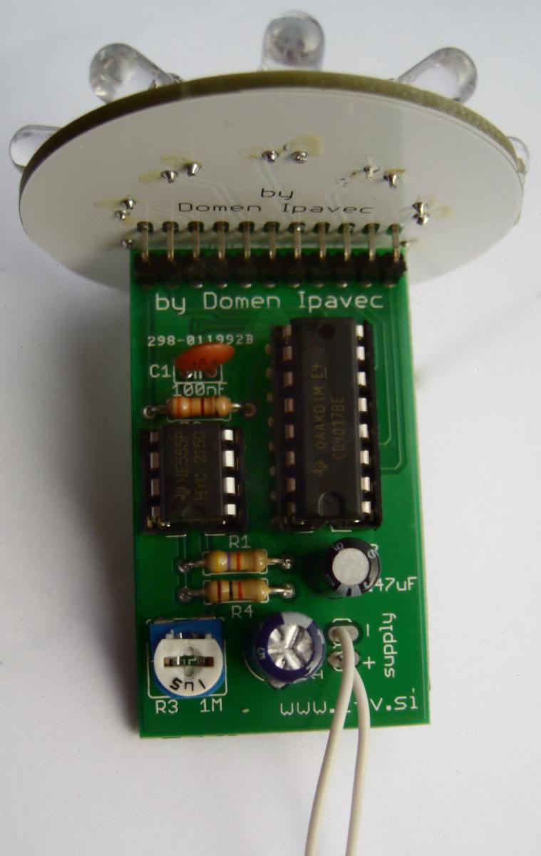
The circuit uses 555 and 4017 integrated circuits to turn each of the 10 LEDs one after another. The LEDs are placed in a circle to create the effect of spining - just like a light in a lighthouse. The speed can be controlled with a variable resistor.
I am selling on tindie:\

Operation
Required skills
- Knowledge of basic electronic components
- Soldering of THT components
Theory
- LED diodes
- 555 integrated circuit
- 4017 IC
The kit for building a DIY lighthouse contains following items
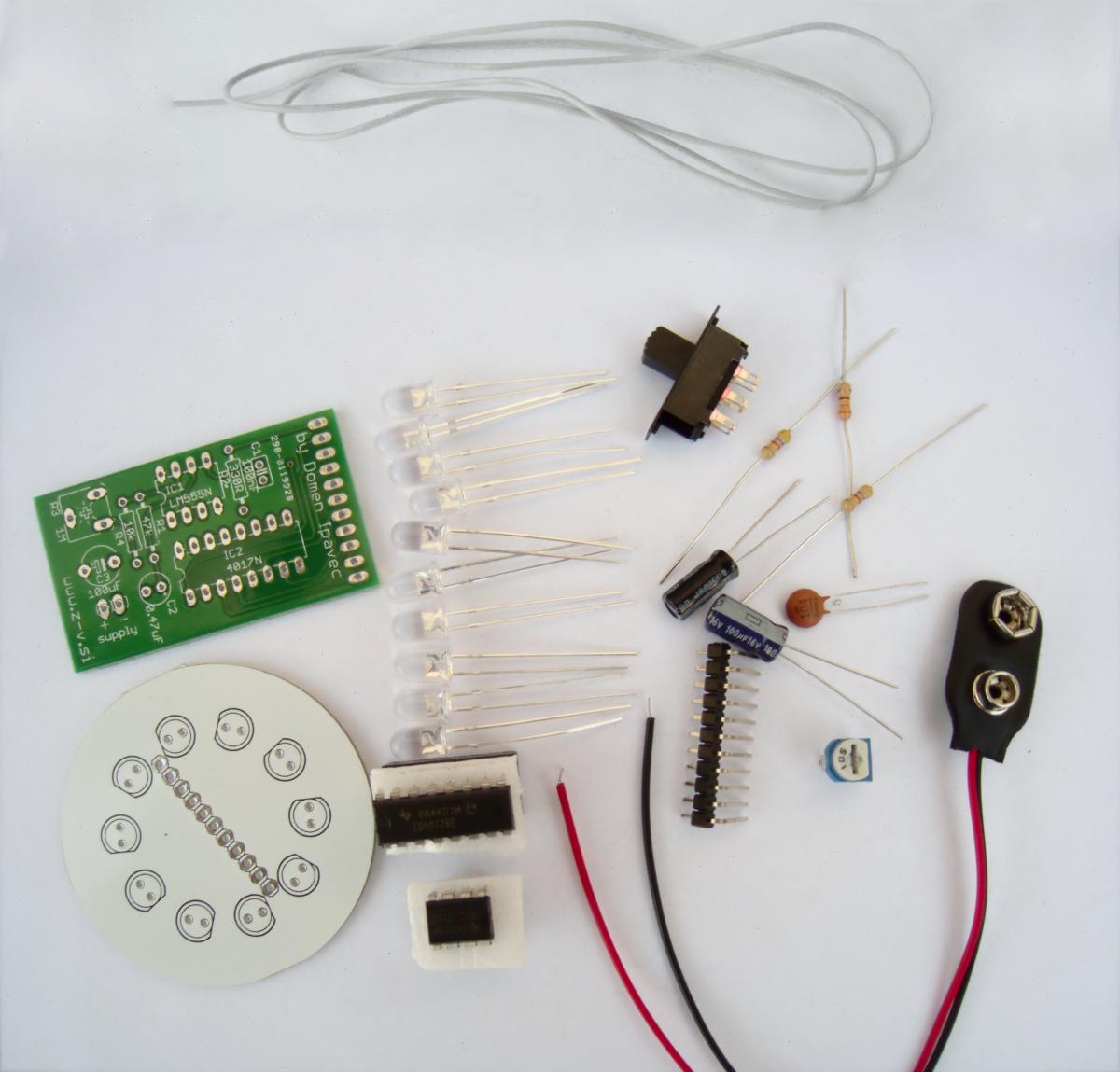
- Main printed circuit board
- 47k, 10k, 330R resistors
- 1M variable resistor (trimmer)
- 100uF, 0,47uF, 100nF capacitors
- 555, 4017 ICs with sockets
- 90 degrees header
- LED pcb
- 10 white LEDs
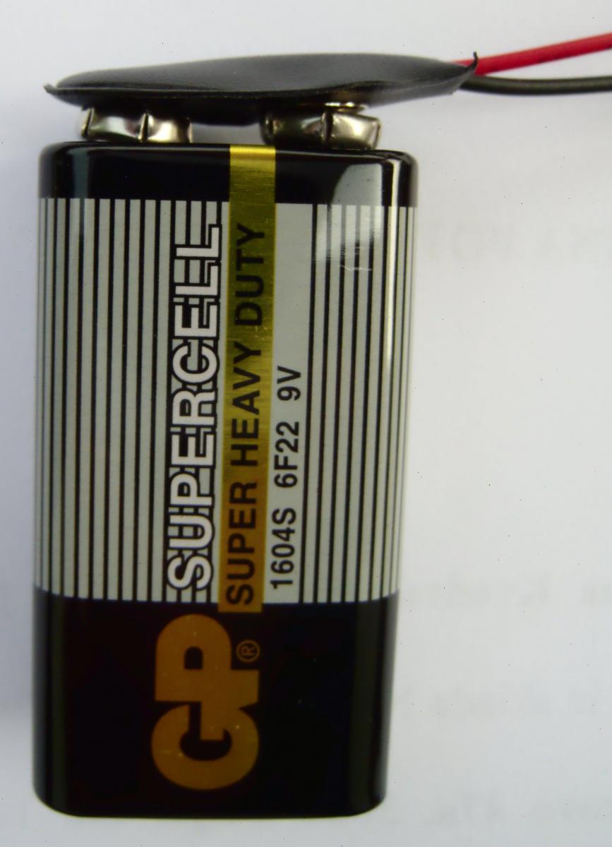
- Battery connector
- Wire
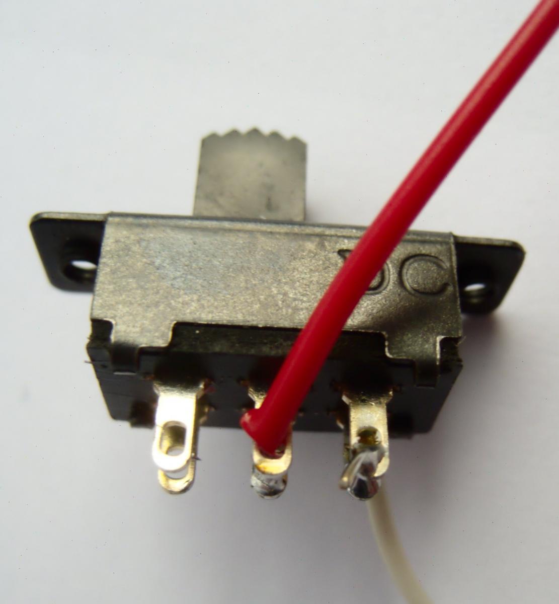
- Switch
Assembly
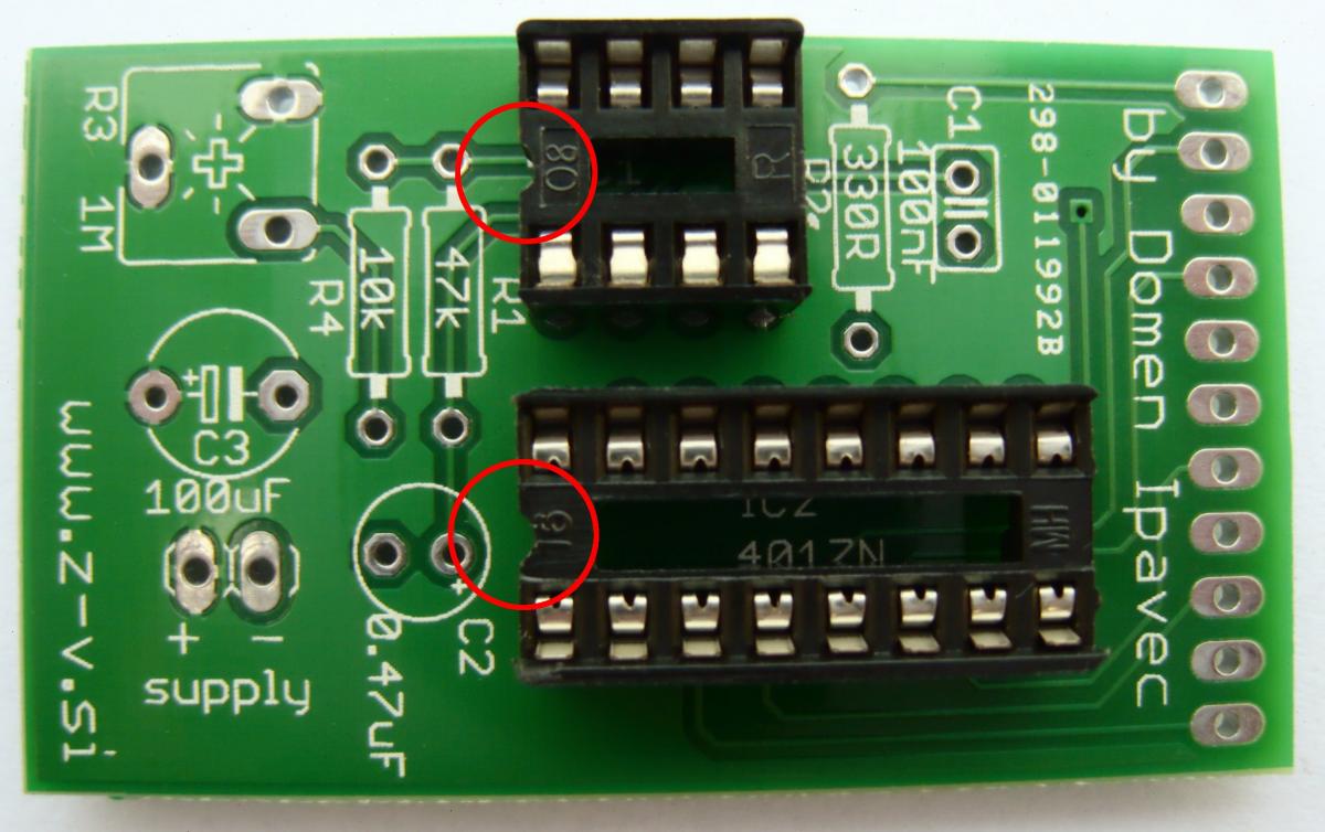
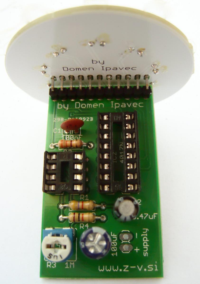
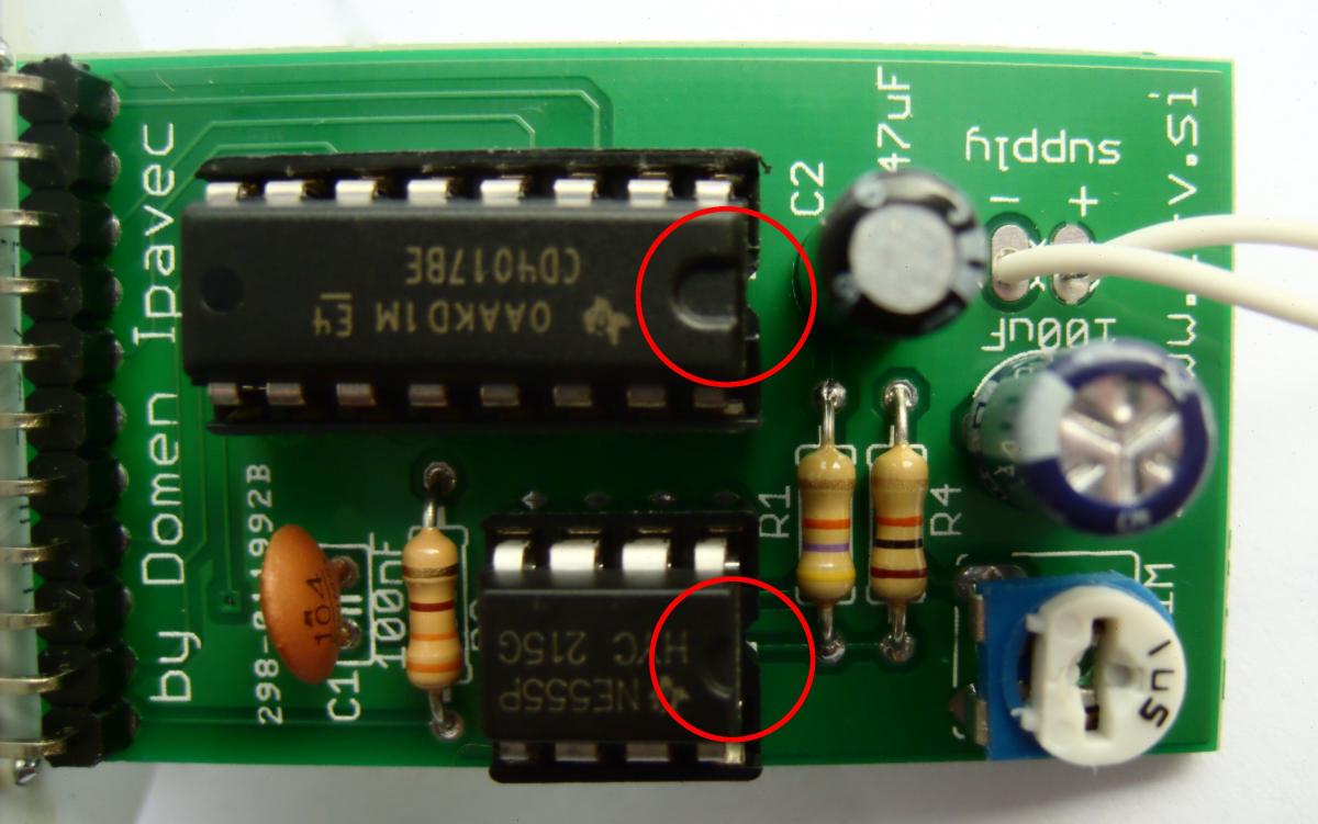
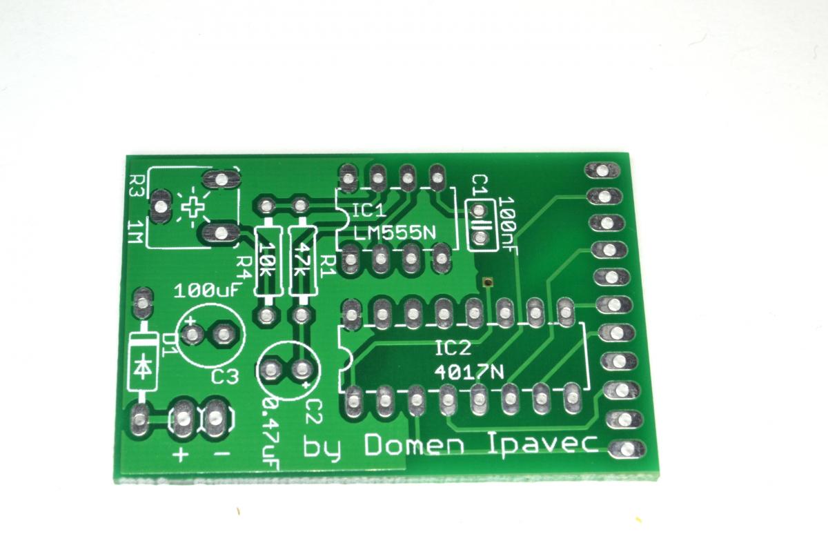
First you have to solder sockets for both ICs on the main pcb (rectangular, green). Be careful to turn them the rightway - the notch has to match the drawing on the pcb.
Then you should solder the three resistors - values are written on the pcb (color codes of the resistors can be found here). You can turn the resistors either way, it doesn’t matter.
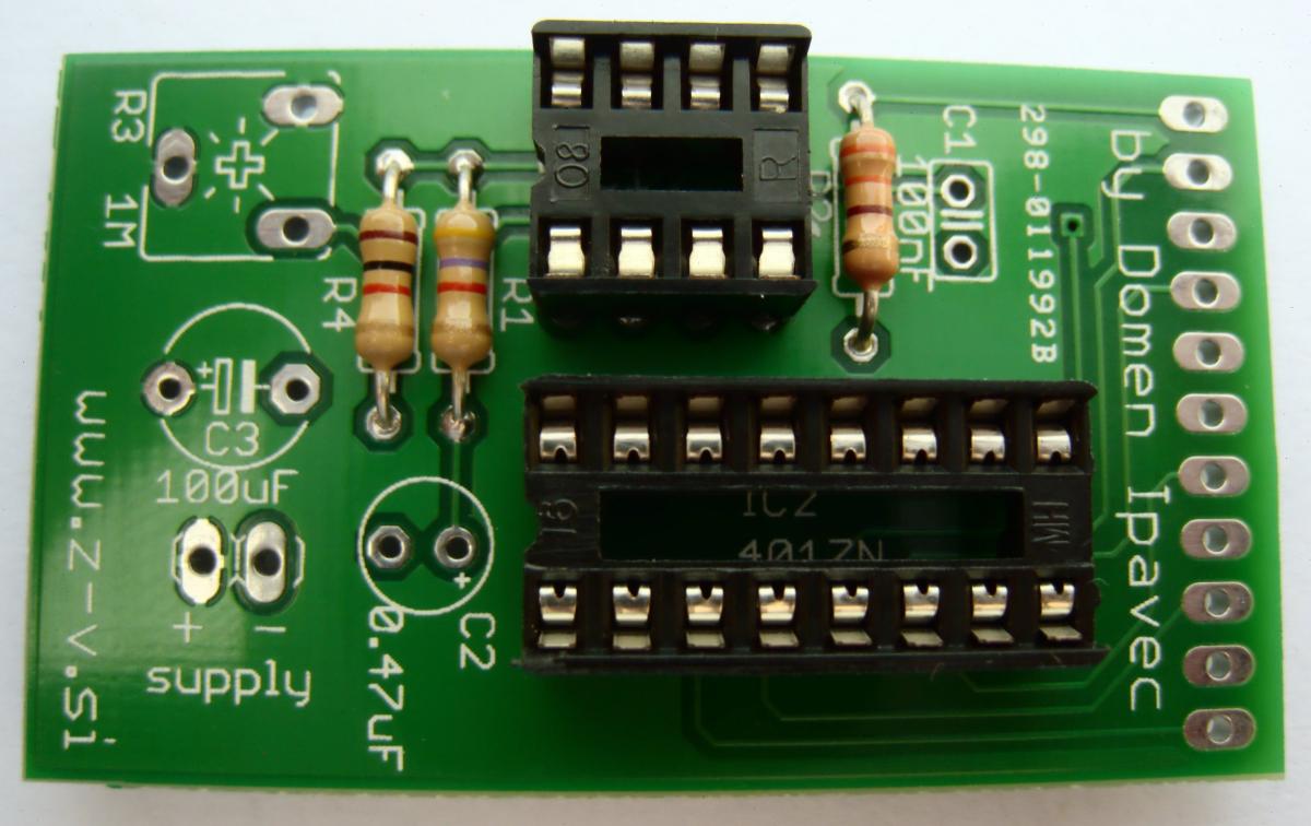
Next you add the header and the variable resistor. Solder the shorter part of the header on this pcb (the one with a black plastic on it).
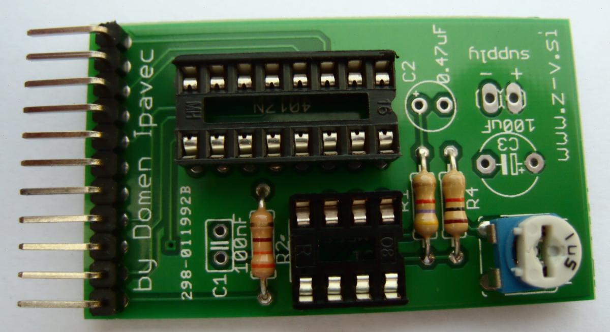
Finally solder the capacitors. Values of the capacitors are written on the pcb. Electrolytic capacitors are polarized, so you have to place them the right way. You can place the ceramic capacitor in any orientation.
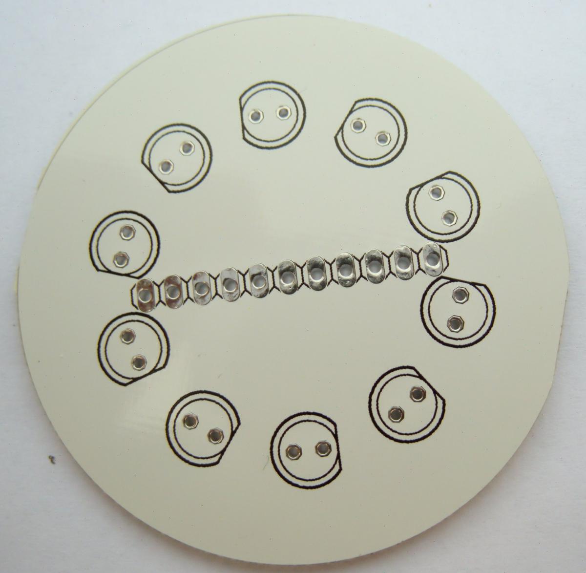
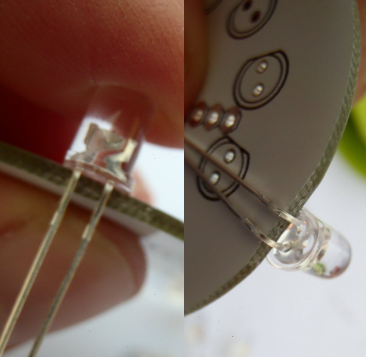
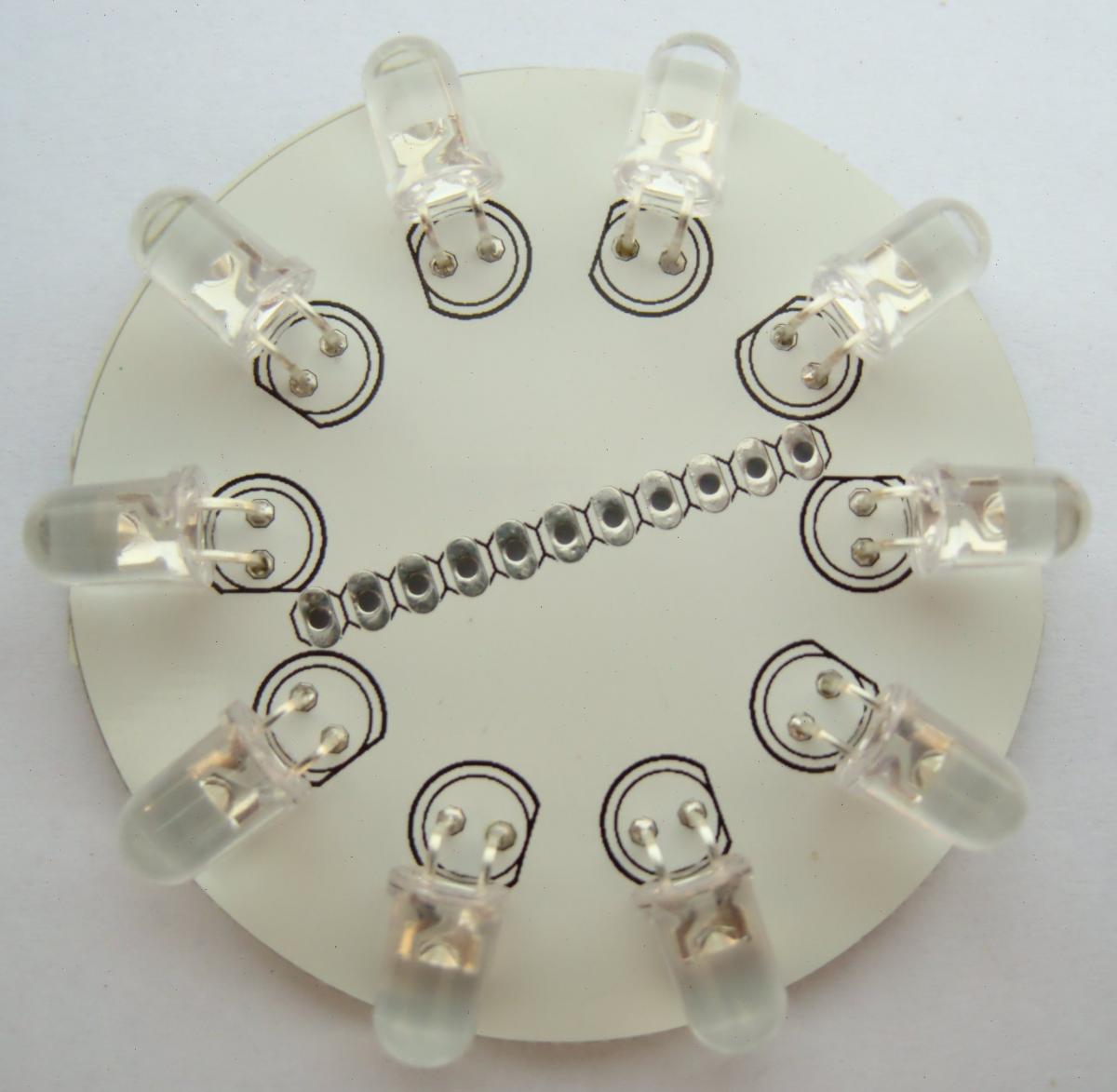
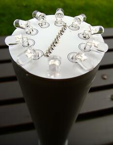
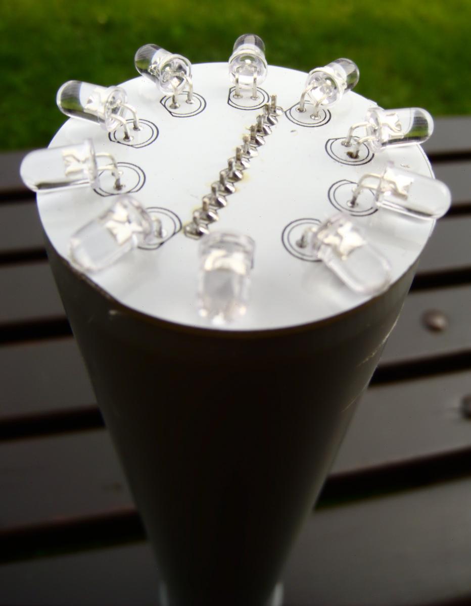
On the LED pcb (round, white) solder 10 white LEDs. Bend the LED leads as shown on the picture, than insert them in the PCB. Be careful to insert them the correct way (longer lead of LED is a positive connection, on the pcb a straight line marks a negative connection).
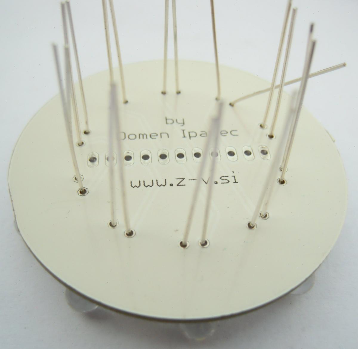
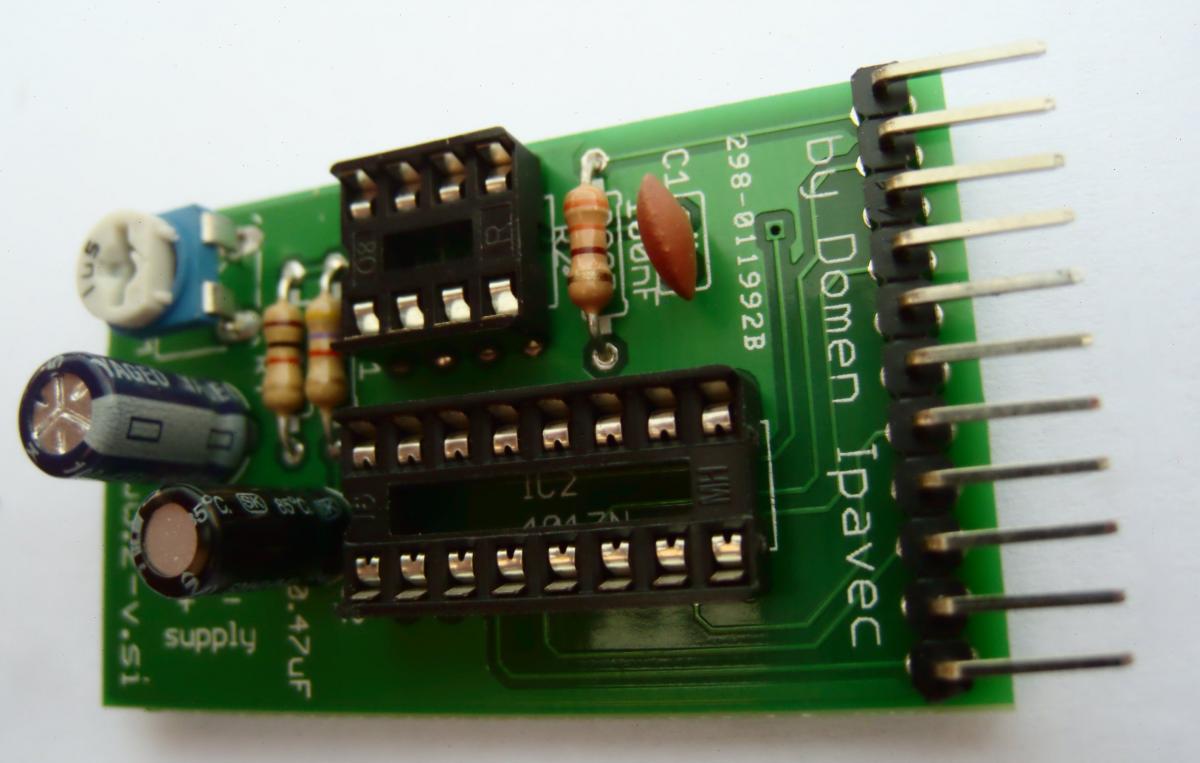
LED pcb solder on the main pcb. Be careful to turn it the right way (inscriptions “by Domen Ipavec” on both pcbs have to be on the same side (see image)).
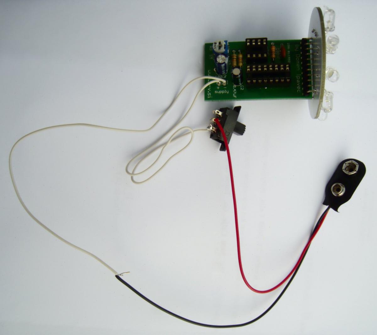
Solder wires on the switch, main pcb and battery connector. The positive battery connection (red wire) has to go on the positive pcb connection (marked with a “+"). Use the middle and one of the border connections on the switch (see image).
Insert ICs in the sockets. Watch that all pins of IC go nicely in the socket (don’t use excesive force, if IC does not want to go in, check all the pins again - bend the pins if necessary). Make sure that the notch on the top of IC matches the notch on the socket and marks on the pcb.
Connect a 9V block battery on a battery connector and turn your new lighthouse on. Adjsut the speed with the variable resistor.
If the circuit doesn’t work check all solder joints and component orientation. If it still doesn’t work contact me or describe your problem in the comments.
Edit 9. september 2014: PCB v2
The new version of PCB for lighthouse is slightly changed:
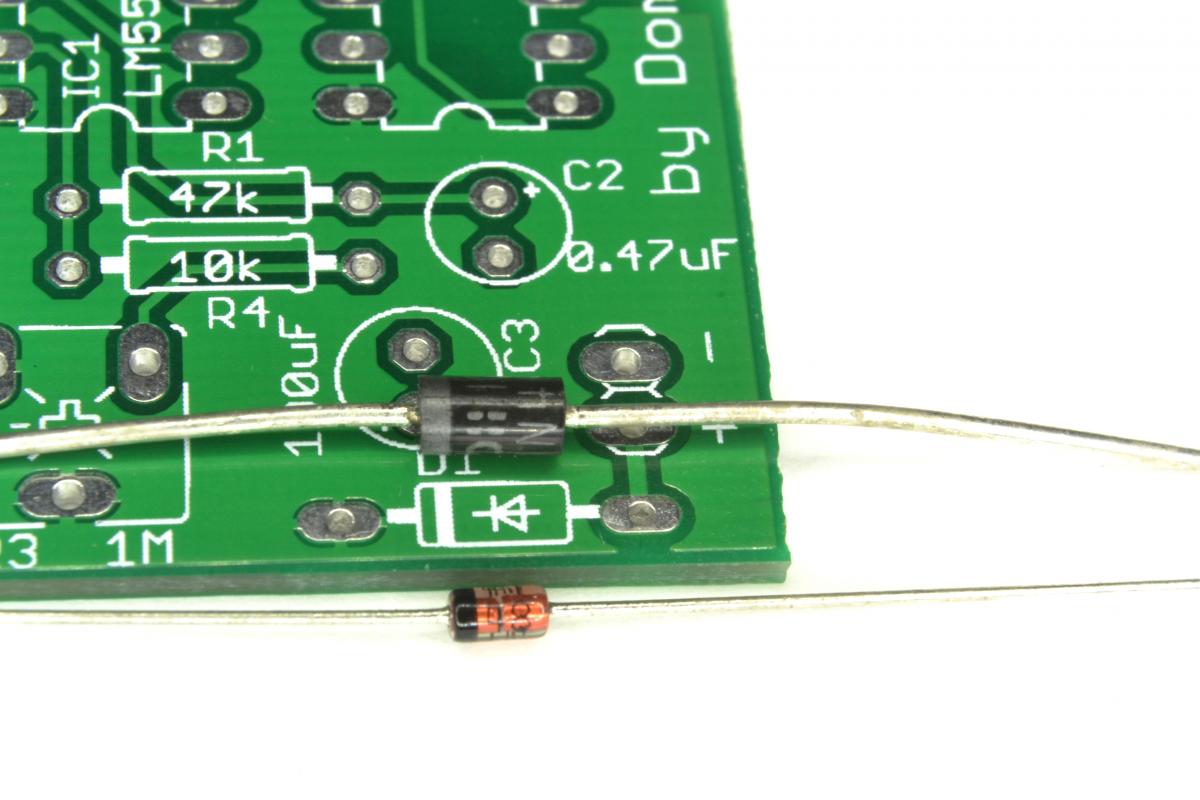
The R2 resistor is removed, because it is not needed. And the diode D1 is added. When soldering the diode, you have to place it the right way. See the image below to see how the diode must be placed. Notice the white line on PCB and black/silver line on the diode, they must be on the same side.
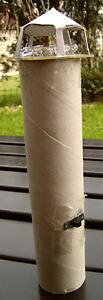
House for the light
Now that you have successfully built your light you need a house for it. A few ideas:
- Grey PVC tube
- Paper towel tube

If you build your own lighthouse with a better house, post a link to the picture in the comments.
Express your opinion and other things on your mind in the comments.