LED Traffic Light
Traffic lights are all around us, and they seem simple enough but are they really? Real traffic lights can be a very complicated system because it requires sophisticated control and coordination for smooth and safe traffic.
The traffic light I made is much simpler. My sister works in a kindergarten where kids needed a simple traffic light for when they are riding their bikes on the playground.
The traffic light uses some cheap LEDs from China, a step-up converter and an Atmel attiny841 microcontroller to change the light from red to green at a programmed interval.
Electronics
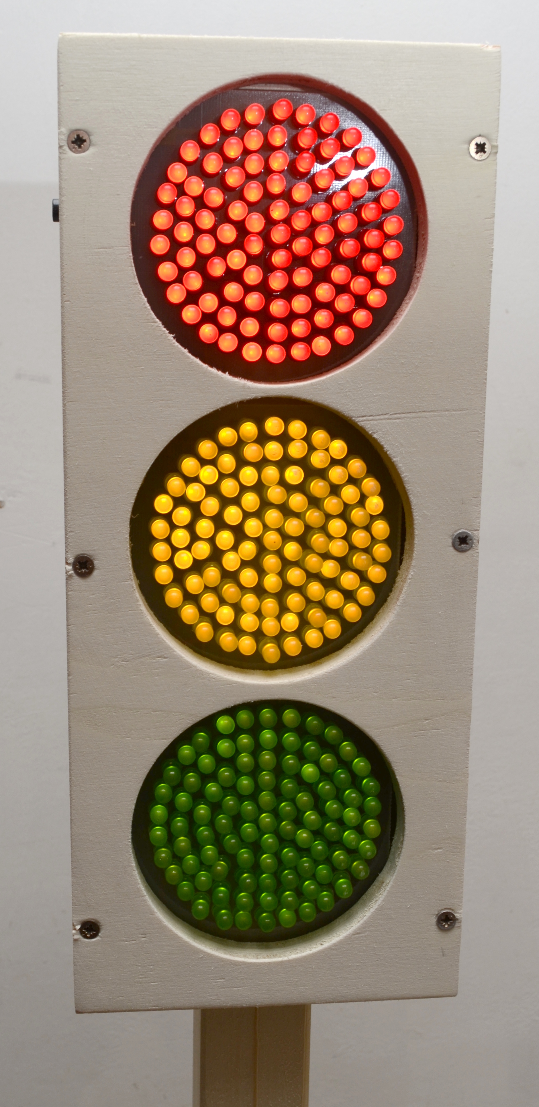
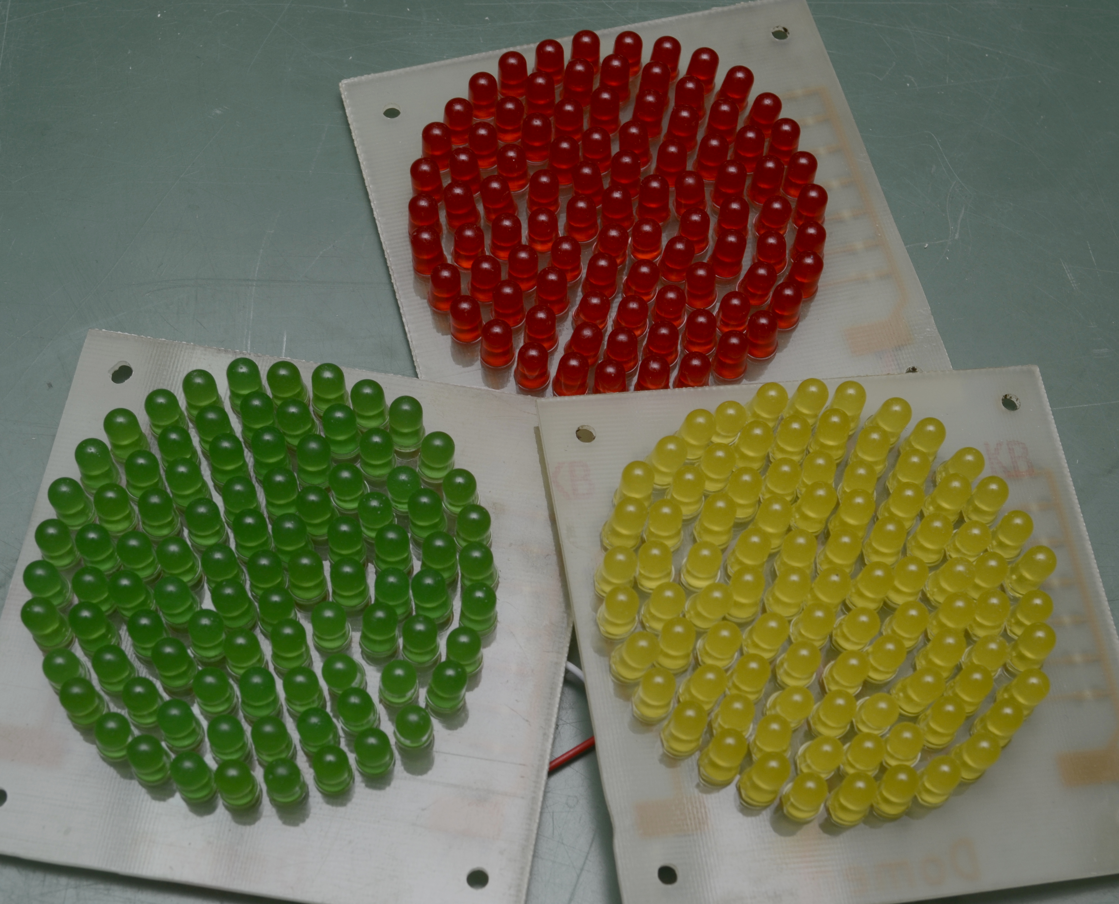
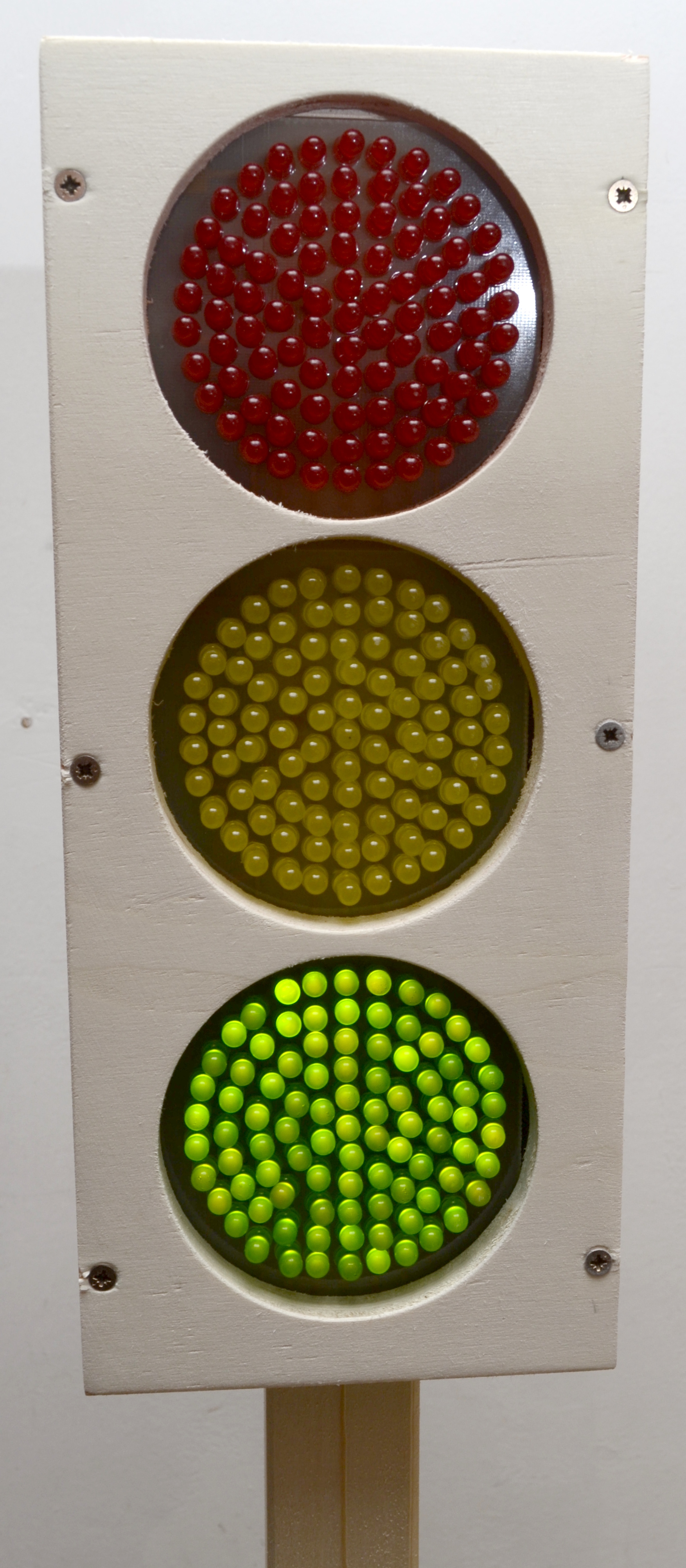
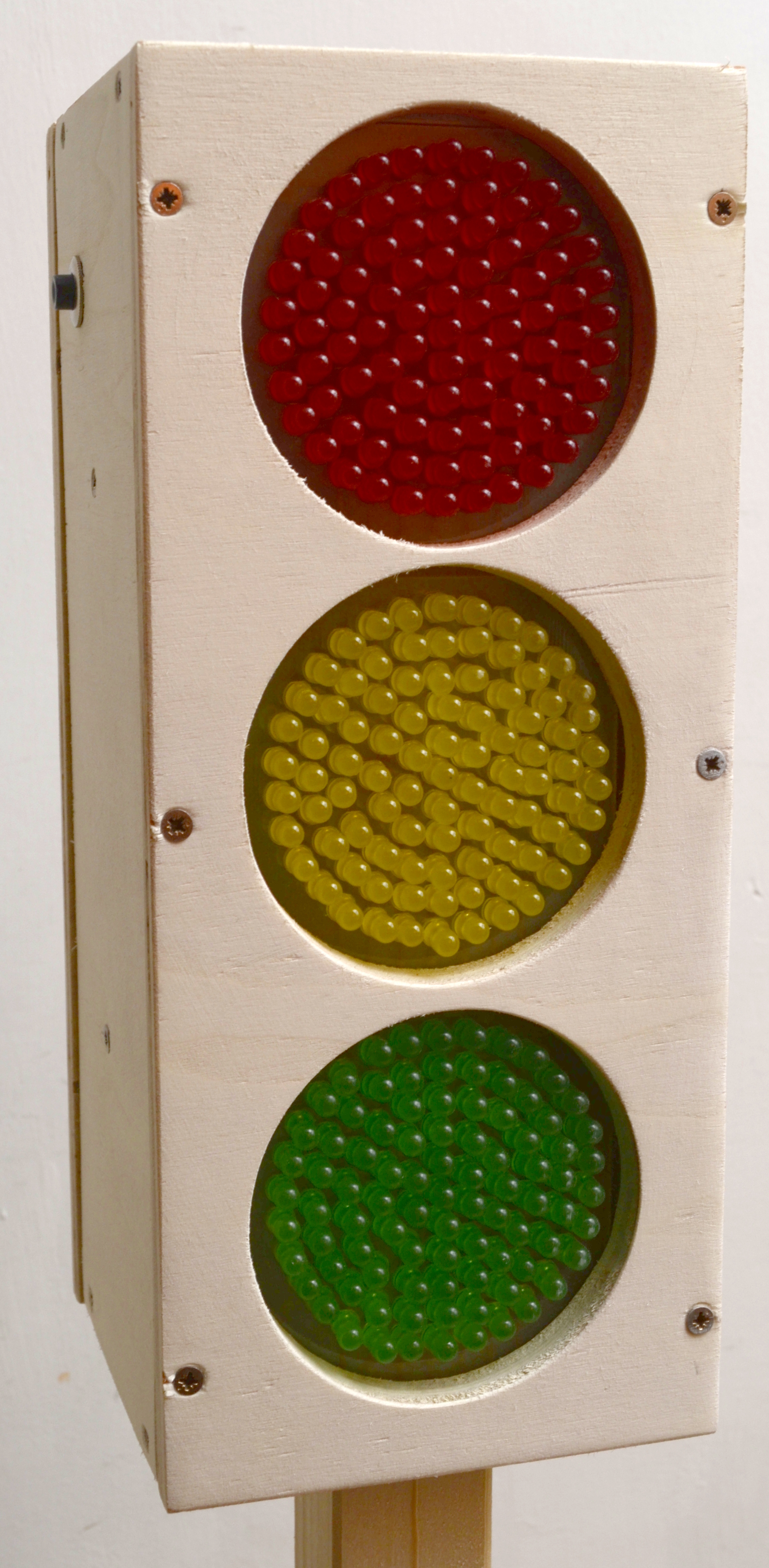
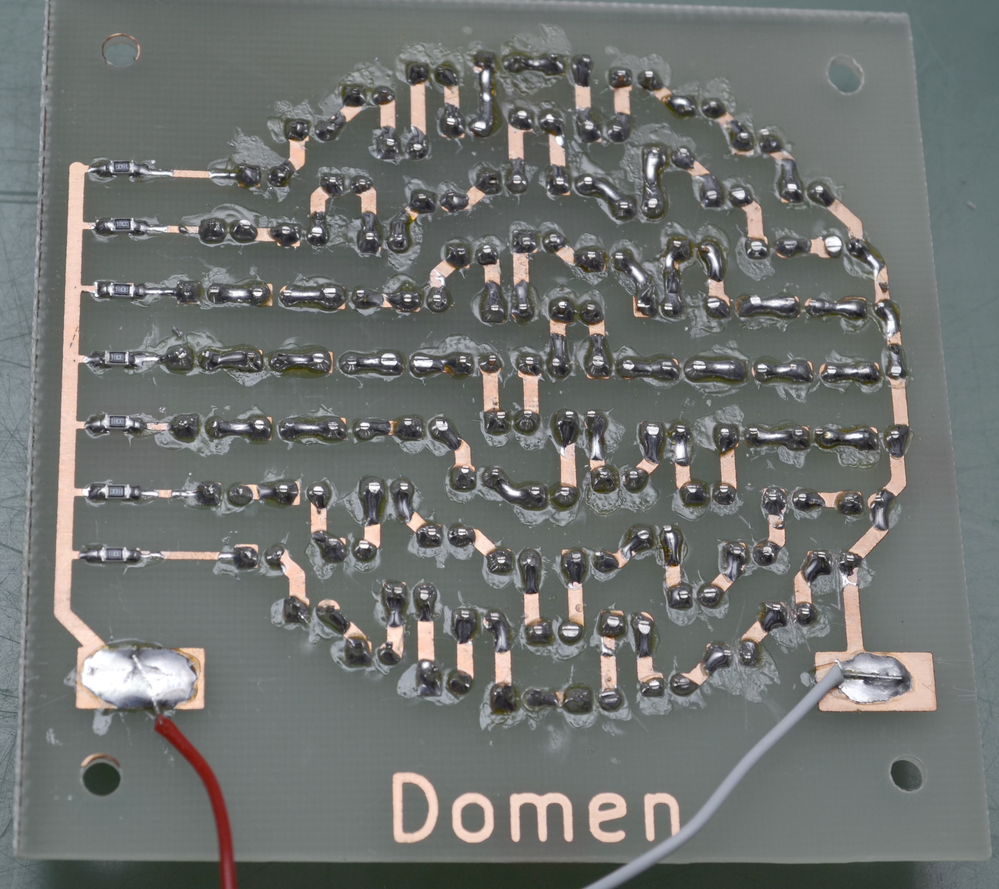 Each light has its own PCB with 91 LEDs that are connected in 7 lines of 13 LEDs and each line has its own series resistor. Resistors are different for each light to compensate for different forward voltages of LEDs (but the green LEDs are still a problem because they are much dimmer than the other two colors).
I have written a python script that uses kicad libraries to arrange the LEDs in perfect circles. This way I was able to experiment with different number of lights in each circle and come up with optimal arrangement. The documentation for python interface with KiCAD is not very good so this was not as easy as I had hoped.
The light PCBs each has a positive and negative terminal that connects to the main controller PCB. The controller uses a step-up converter to boost the battery voltage up to 30 volts required for the LEDs. The step-up controller works in the open-loop configuration. The switching mosfet is controlled by the attiny microcontroller and the pwm duty cycle is determined only based on the input voltage. That works well enough for the constant load of LEDs. Because the battery voltage is measured and duty cycle adjusted, the LEDs brightness is approximately constant during the battery discharge.
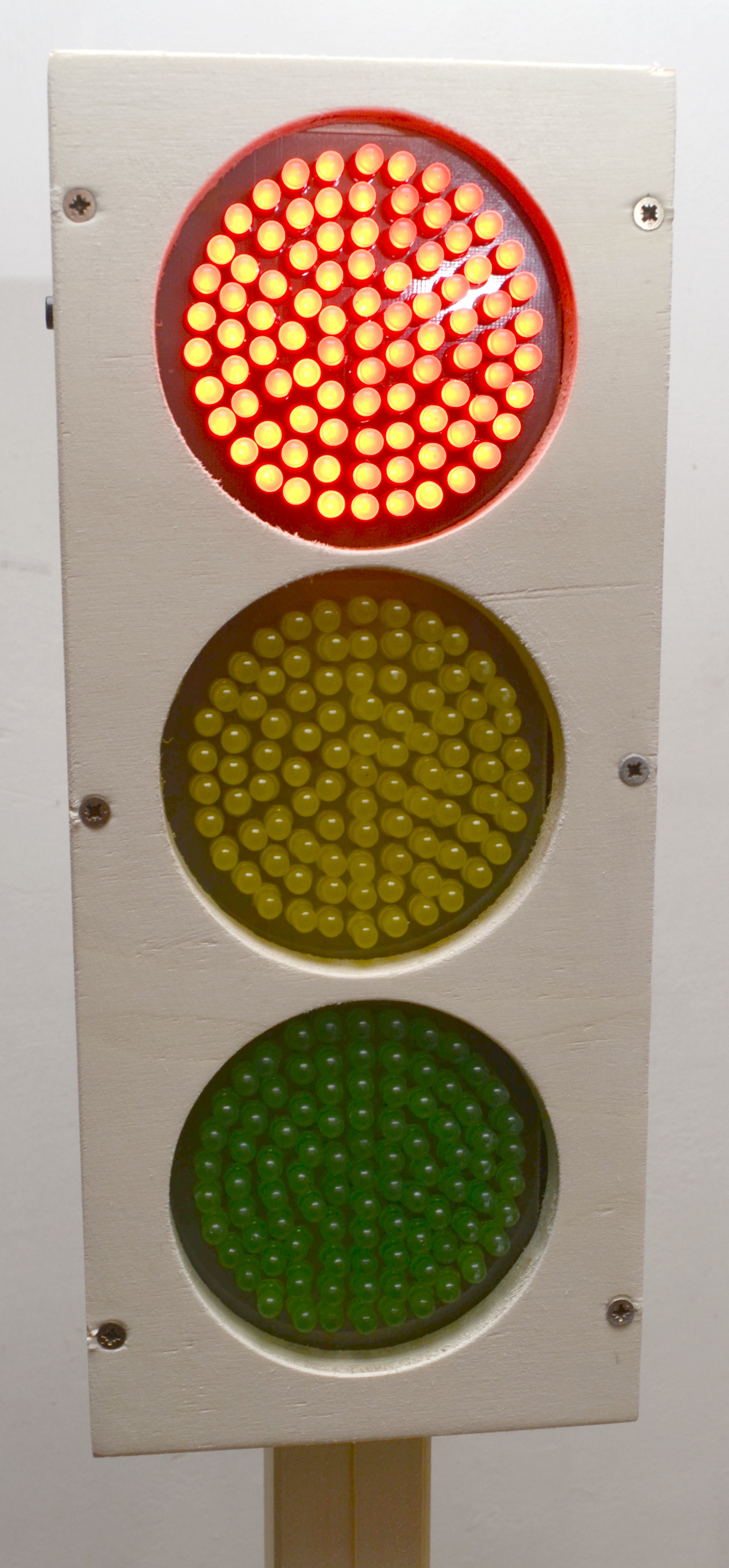
 The attiny841 also monitors the battery voltage and shows battery charge state when the device is turned on. When the battery is full the green light blinks, when it is half-full the yellow light blinks and when the battery is almost empty the red light blinks. When the battery is practically empty the device also automatically turns off.
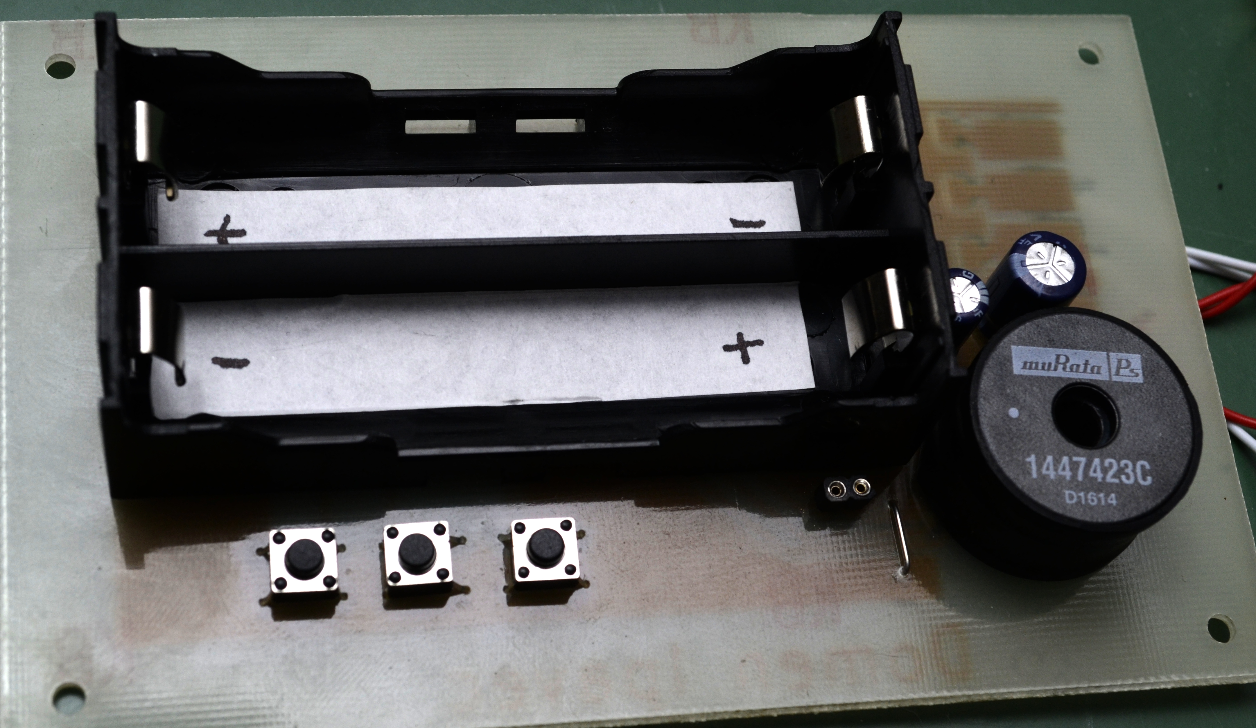
The power switch is connected to the mosfet in series with the battery supply so the turned off current is 0. I have made the mistake on my pcb version and turned the mosfet the wrong way around and the circuit was powered through the mosfet diode even when turned off. This is fixed in the schematic and pcb, but the pcb is missing the reverse polarity mosfet - that is the second mosfet in that mess on the pcb. Stay tuned for my article next week that will describe the power switch and mosfet polarity protection in more detail.
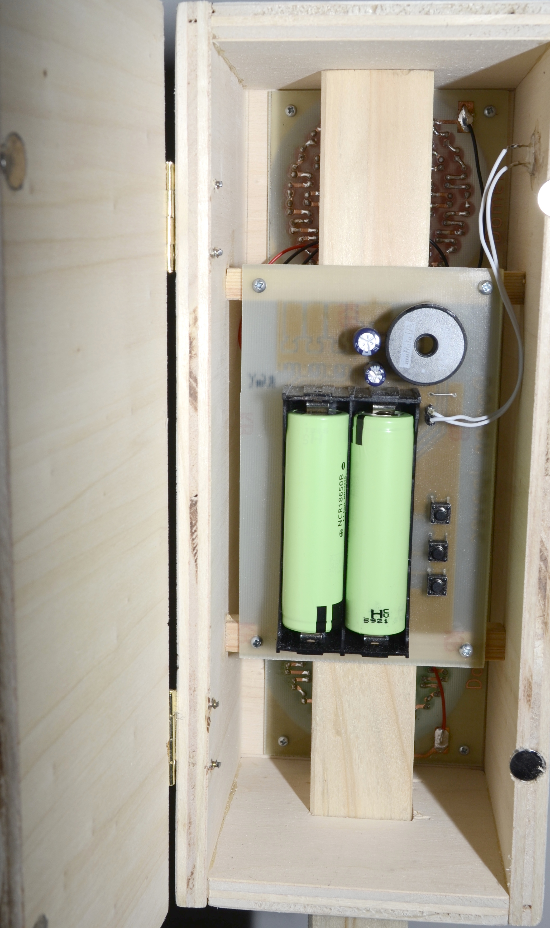
The power is supplied by two 18650 rechargeable lithium batteries. Because I used high capacity 3000mAh batteries they should by my calculations last 20 hours, more than enough for an afternoon of children playing. The required voltage (5 volts) for the microcontroller is regulated with a linear regulator.
Case and Stand
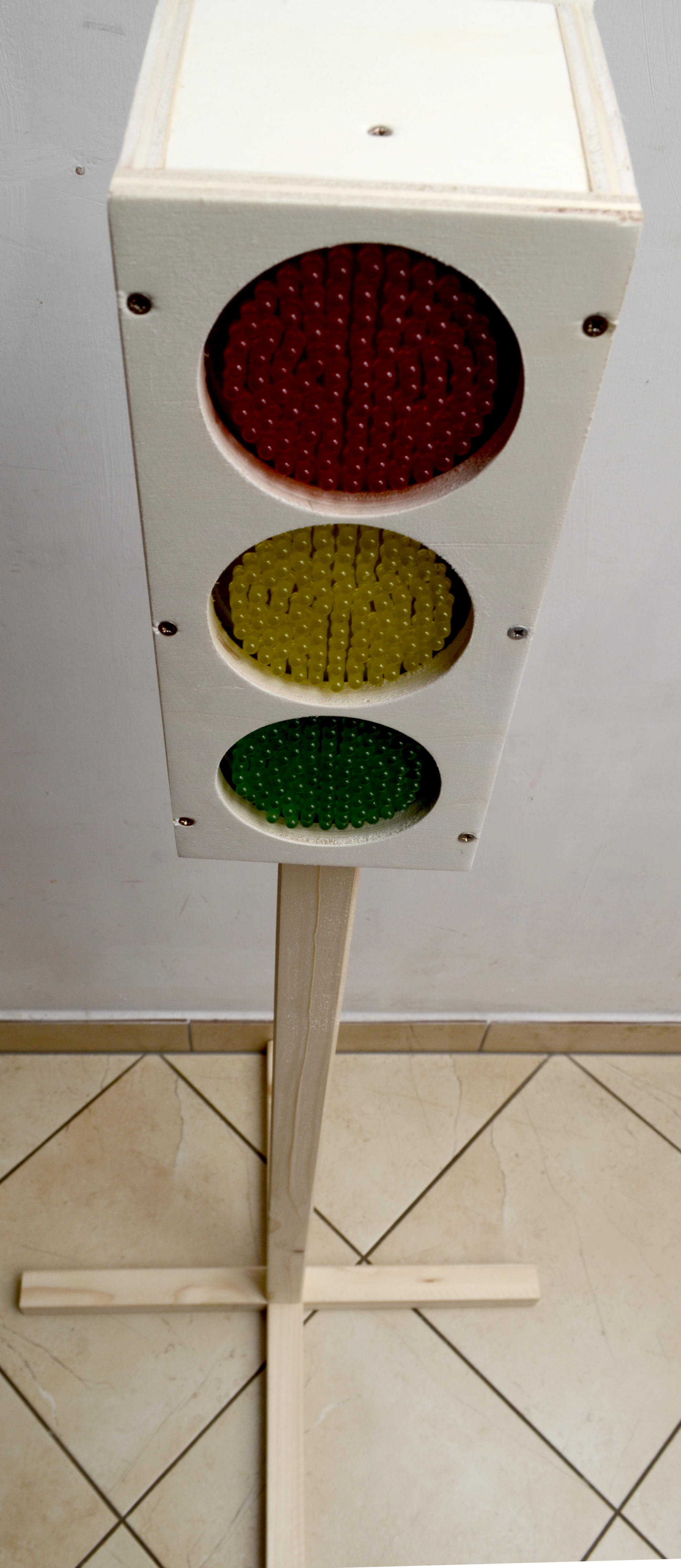
The main body of the traffic light is made from 1cm thick plywood and is glued and screwed together. The back side is on hinges and can be opened to replace the batteries (or get them out for charging) and access the three buttons that are on the inside. The door is held closed by two pairs of small magnets that are hot glued to the wood.
The stand is made from 33mm wooden beam, the bottom forms a + and is screwed and glued to the vertical beam.
User interface
 The traffic light has one power button on the outside of the unit. It powers the unit up when pressed, and turns it off when pressed for long time (3 seconds). When turned on, the first light that blinks indicates the battery charged status.
The brightness of the LEDs can be adjusted with the up and down buttons inside the battery compartment.
The traffic light can operate in three modes, that are changed with the middle button in the battery compartment:
- The traffic light changes automatically with a set interval.
- The traffic light changes manually when the power button is pressed.
- The yellow light blinks.
The interval for the automatic mode can be set with a long press to the button that is used for changing the mode. The red and green light will blink simultaneously and the timer will start measuring time. You can then press the power button at any time to change the light and the elapsed time will be used as interval for next changes.
Video
Here is a short video clip of the working traffic light:
Files
- Schematics: controller.pdf
- Github repository: traffic-light
Images