USB AVR programmer
I’ve already had a programmer for Atmel’s AVR microcontrollers, but I couldn’t use it in my lab, because my laptop doesn’t have a LPT port. So I decided to make a new programmer with USB connection. I’ve found an open source programmer AVR doper, and for the basis I took a modified version from the http://www.kreuzholzen.de web page. I designed a new singled sided PCB board, that I was able to make at home. The programmer is compatible with STK500v2.
Schematics
USB connection

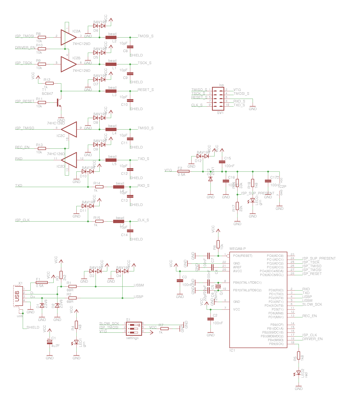
I used a male USB type A connector, so that I can plug the programmer directly in the laptop’s USB port or I can use a USB extension cable. The USB supply is protected with a 500mA PTC resettable fuse on positive lead. To convert the USB data lines from 5V on microcontroller, to the lower voltage used by USB, we use 3.6V zener diodes, that must be fast low current type, and 68ohm resistors. USB D- line is pulled up with 2k2 resistor. This is required for the computer to correctly recognize USB device (for more info you can read the article). For ESD protection we use double diode BAV99 from signal to GND and supply. We also have a 4.7uF electrolytic capacitor on the supply. We can use a LED diode for indication of USB supply. I used a low current LED diode with a 1k8 resistor, if you will use standard diode, you shuld use a lower value resistor.
Microcontroller
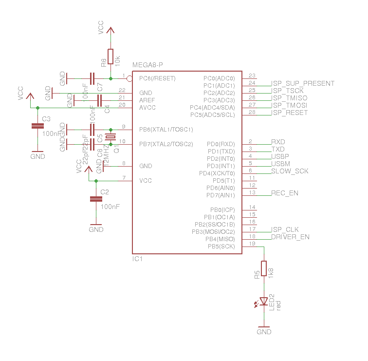
The programmer is controlled with an ATMEGA8 microcontroller. The microcontroller is clocked with 12Mhz crystal with 22pF capacitors. We put the decoupling capacitors (100nF) on microcontroller supply pins and AREF pin. Reset pin is pulled up to 5V with a 10k resistor and protected against interference with 100nF capacitor. On pin PB7 is a LED diode, indicating the programming in progress. The signals are connected to avr as indicated in schematics.
Voltage level shifter, interference and ESD protection
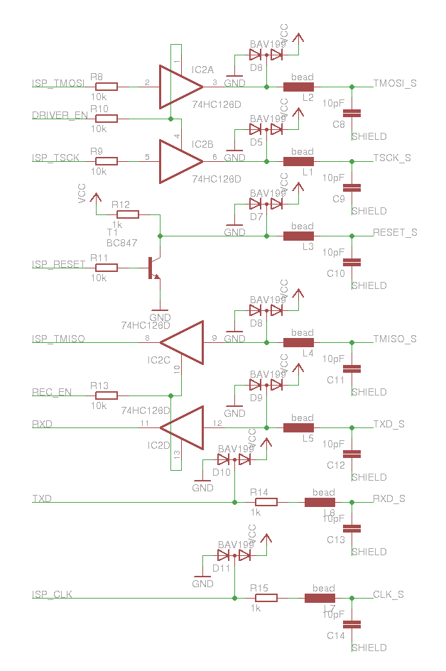
To convert voltage levels from microcontroller from programmer to the programmed microcontroller we use 74hc126. On all signal lines is also a bav99 diode for ESD protection and beads and 10pF capacitors to USB shield against interference.
DIP switch for settings
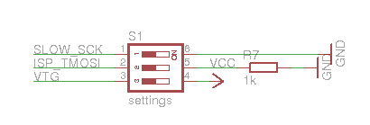
Three settings are available on avr programmer:
- Connecting pin SLOW_SCK from microcontroller to GND sets lower programming speed. We can use this setting if our software doesn’t support it. The lower speed of programming is needed when the programmed Atmel microcontroller runs at lower frequency (such as for example 32kHz).
- Pin ISP_TMOSI pulled to GND with 1k resistor. This settings select the type of USB device the programmer emulates. The recommended setting is the switch in connected position. This sets the type of device to HID, otherwise the device of our programmer will be a serial modem.
- With this setting we connect the supply of programmer to the supply of programmed avr, so the programmed chip can as well be supplied from the USB port.
Output supply
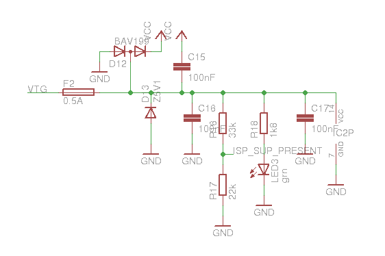
VTG is connected to one of ISP pins to provide the voltage of the programmed avr, but if we select the setting we can use it to supply the programmed microcontroller with voltage from USB. The TVS diode D13 is used to protect input voltages above 5.1V, bav99 double diode handles ESD and capacitors filter interference. The LED diode indicates voltage on the output, and with the voltage divider the voltage is connected to ADC pin of programmer’s avr. The 74hc126 is also supplied from output voltage, so that is can convert programmer’s signals to the required voltage of programmed microcontroller.
ISP connector
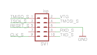
The first 6 pins of the connector match the standard 6-pin ISP connector. The 10 pin connector does NOT match the standard ISP. On pin 9 is a CLK signal, that can be used to programme the microcontrollers with the fuse bits set to external clock. On pins 8 and 10 we have RxD and TxD serial communication pins, that can be used for serial communication between computer and the programmed microcontroller, for example to debug our programmes. Current version of software only supports one-way communication from avr to computer, which is enough for simple debugging purposes.
Complete schematics
Or in eagle format: avr-programator.sch
Manufacture
PCB
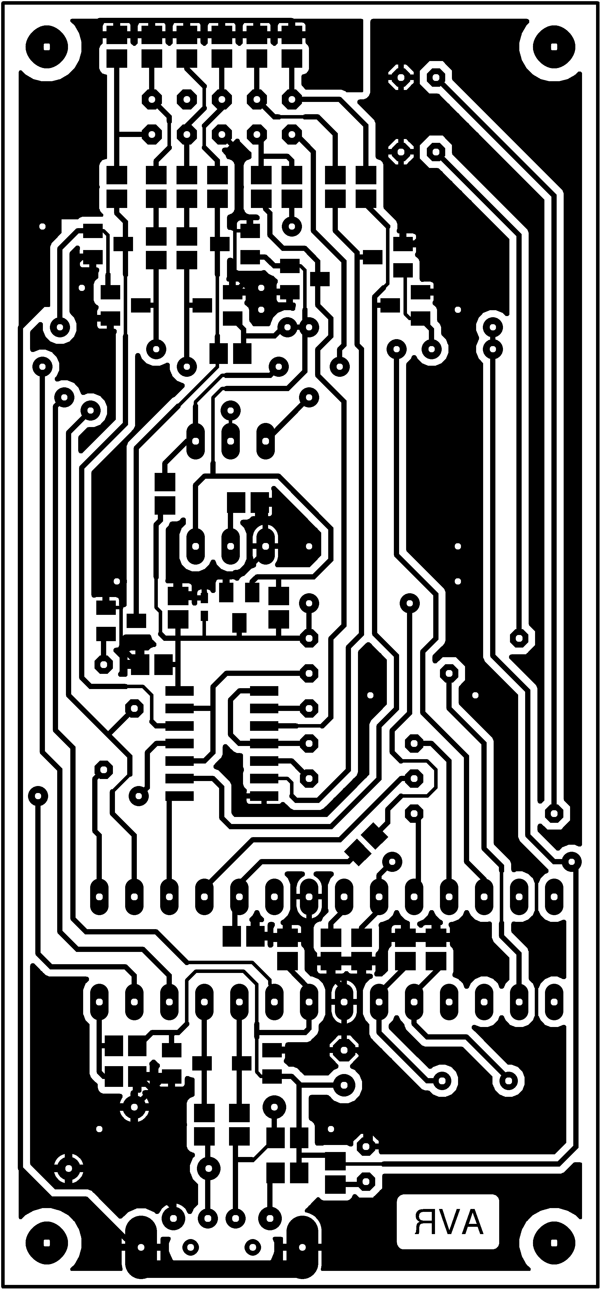
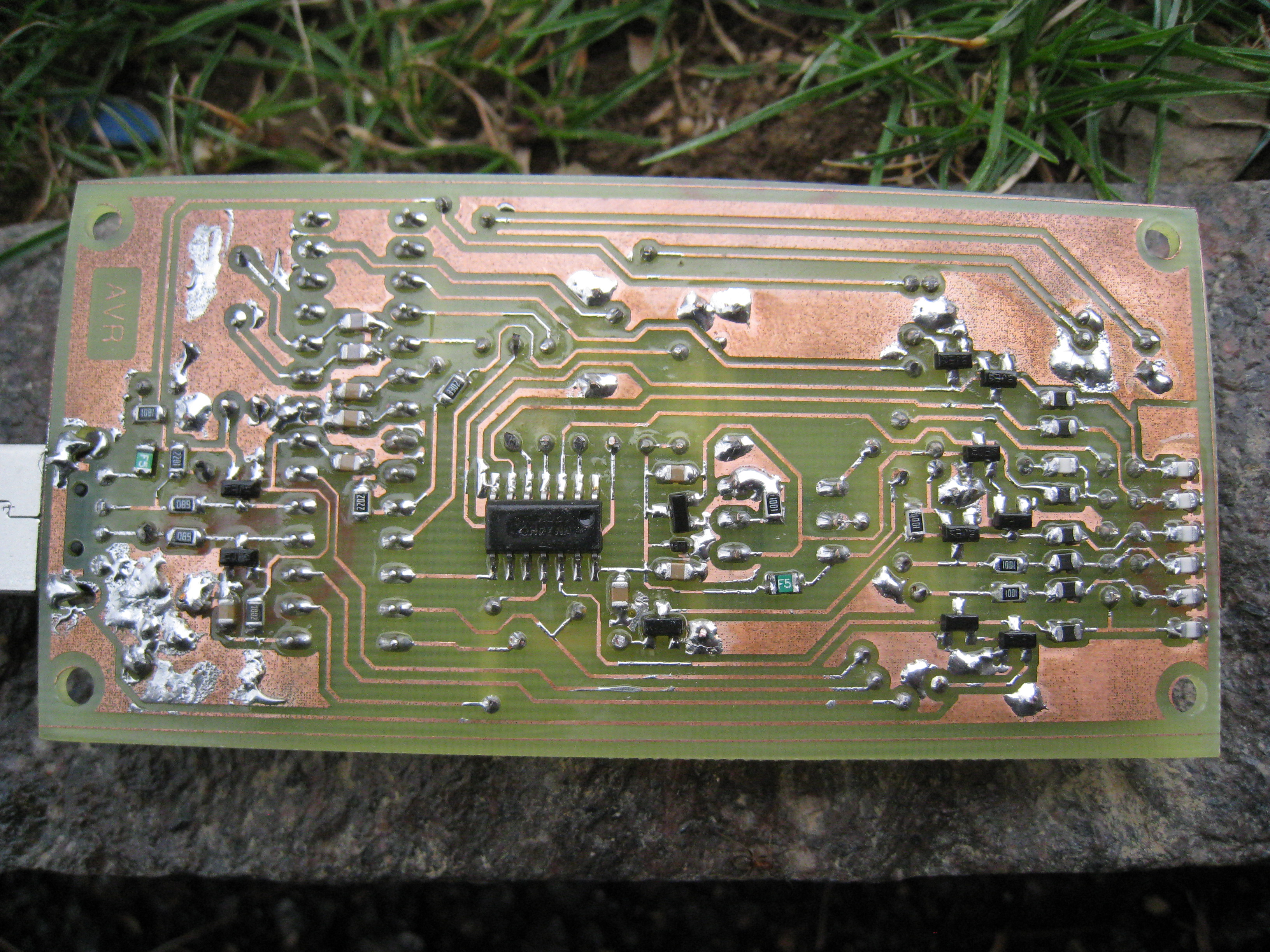
The Printed Circuit Board for this programmer is a quiet compact one sided board. Components used are SMT as well as THT. Because of the compact design I will not give the image with components layout, bacause it would be more or less useless. The layout can be viewed on PCB in Eagle file. For the top layer connections (red color in eagle), the wires can be used. The PCB can be easily produced at home, but requires some soldering skills for soldering SMT components.
Components list
| Name | Quantity | Price per item [€] | Price [€] | Farnell product number |
|---|---|---|---|---|
| USB connector | 1 | 0.67 | 0.67 | 1696544 |
| PTC fuse | 5 (2)* | 0.16 | 0.81 | 1861197 |
| Zener diode 3.6V | 2 | 0.02 | 0.05 | 1861444 |
| BAV99 double diode | 10 | 0.05 | 0.47 | 1617739 |
| Crystal 12Mhz | 1 | 0.42 | 0.42 | 1842203 |
| Resistor 10k 0805 | 1 | 0.02 | 0.02 | 1612522 |
| 74hc126 | 1 | 0.35 | 0.35 | 1013851 |
| Bead 0805 | 7 | 0.02 | 0.12 | 1611983 |
| Capacitor 10pF 0805 | 10 (7)* | 0.04 | 0.38 | 1800820 |
| Transistor bc847 | 1 | 0.04 | 0.05 | 1653607 |
| ATMega 8 | 1 | 2.47 | 2.47 | 1748534 |
| TVS diode 5V | 1 | 0.08 | 0.08 | 1829230 |
| Red LED diode | 1 | 0.17 | 0.18 | ** |
| Green LED diode | 2 | 0.17 | 0.35 | ** |
| Resistor 68R 0805 | 2 | 0.03 | 0.06 | ** |
| Resistor 2k2 0805 | 1 | 0.03 | 0.03 | ** |
| Resistor 1k8 0805 | 1 | 0.03 | 0.03 | ** |
| Electrolytic capacitor 4.7uF | 1 | 0.08 | 0.08 | ** |
| DIP switch 3 | 1 | 0.45 | 0.45 | ** |
| Resistor 1k 0805 | 4 | 0.03 | 0.12 | ** |
| Capacitor 22pF 0805 | 2 | 0.07 | 0.14 | ** |
| DIP28 0.3" socket | 1 | 0.57 | 0.57 | ** |
| Resistor 22k 0805 | 1 | 0.03 | 0.03 | ** |
| Resistor 33k 0805 | 1 | 0.03 | 0.03 | ** |
| Speedy (IDC) connector | 1 | 0.24 | 0.24 | ** |
| Resistor 1k8 | 2 | 0.05 | 0.10 | ** |
| Capacitor 100nF 0805 | 7 | 0.01 | 0.06 | ** |
| Resistor 10k | 5 | 0.02 | 0.11 | ** |
| Sum | 74 (68)* | 8.47 |
* Number in brackets is needed, but there is a minimal quantity required. \
** Can be bought in local electronics shop.
Finished programmer
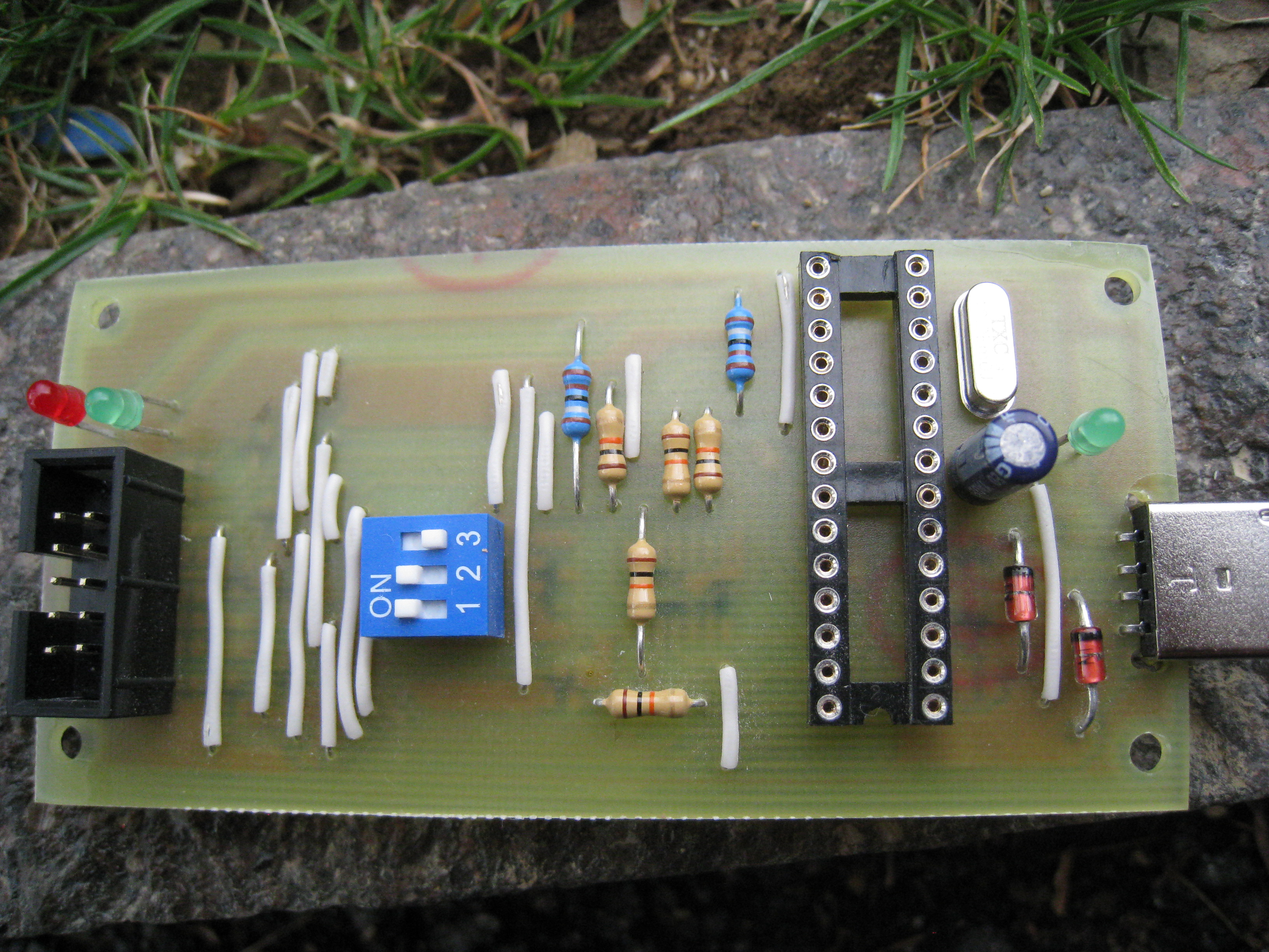
The microcontroller requires a socket, so we can programm it (if we fail in first try (like I did) or for a firmware upgrade).
Programming microcontroller
We need another programmer to programme the AVR in our programmer. We can build a simple LPT programmer or borrow a programmer from a friend.
I took a source code from http://www.obdev.at/products/vusb/avrdoper.html and patched it with changes from http://www.kreuzholzen.de/projects/mdoper/index_en.html. When we compile the source code we get the hex file, that we programme our AVR microcontroller with.
- Patched source code: firmware.tar.gz
- Hex program: main.hex
If you use avrdude to programme your AVR microcontroller, here is what the command should look like: \
avrdude -p atmega8 -e -U flash:w:main.hex:i
And we have to set fuse bits:\
avrdude -p atmega8 -U hfuse:w:0xc9:m -U lfuse:w:0x3f:m
Using the USB AVR programmer
Once the microcontroller of our programmer has been programmed, we can finally use our programmer. Once connected to your PC in HID mode, a Linux command dmesg should display something like this:
[16675.052069] usb 5-2: new low speed USB device using ohci_hcd and address 2
[16675.228094] usb 5-2: New USB device found, idVendor=16c0, idProduct=05df
[16675.228101] usb 5-2: New USB device strings: Mfr=1, Product=2, SerialNumber=0
[16675.228107] usb 5-2: Product: AVR-Doper
[16675.228110] usb 5-2: Manufacturer: obdev.at
[16675.228267] usb 5-2: configuration #1 chosen from 1 choice
[16675.259524] generic-usb 0003:16C0:05DF.0003: hiddev1,hidraw2: USB HID v1.01 Device [obdev.at AVR-Doper] on usb-0000:00:12.1-2/input0
To use our new USB AVR programmer we set the type of programmer to stk500v2 and port to avrdoper - that is needed to override the default serial connection. With avrdude the command looks something like this: \
sudo avrdude -c stk500v2 -P avrdoper ...
Conclusion
Although I haven’t really tested the programmer with Windows, it should probably work without a problem.
I haven’t tested the serial debugger yet, but I will write something about that as soon as I do.
If you have any question, suggestion or a problem, feel free to contact me.
Sources
- http://www.obdev.at/products/vusb/avrdoper.html
- http://www.kreuzholzen.de/projects/mdoper/index_en.html